 עברית
עברית English
More information
Electromagnetic methods (EM) are utilized for environmental, geological and archeological applications, and in recent years – for agricultural applications as well. These methods were developed for the purpose of measuring the electrical conductivity of the subsurface. Since electrical conductivity varies with changes in the medium's composition, for example – water and mineral content, voids, fissures and various other parameters, it is possible to obtain a map of the subsurface's electrical conductivity distribution.
EM methods are based on magnetic induction, and do not require direct contact with the ground – which facilitates field work. EM methods were first developed in the 1920s in Scandinavia, the USA and Canada for mapping metal deposits. Until the 1960s, EM devices were used to carry out measurements through continuous transmission and reception in one frequency. In later years, systems transmitting concurrently in a number of frequencies and using several sensors for reception in parallel were developed, in order to enable reconstructing a vertical section of the measured soil's properties. EM systems that transmit and receive concurrently, enabling to receive a vertical section through changes in the frequency used, are called Frequency Domain systems (FEM, FDEM). In the 1960s, initial attempts were made to construct systems that receive the soil's reaction during the turn-off times in transmission. This approach has become more widespread since the 1970s. EM systems that measure the variations in the measured value measured as a function of time are called Time Domain (TEM, TDEM). The most significant advantage of this method is that the received signal represents the ground's reaction only, without the interference of the initial electromagnetic field transmitted by the device.
Frequency-based EM methods (FDEM)
FDEM instruments usually operate at frequencies of tens of Hz to tens of KHz, and are used for surveying a wide range of depths and targets in the shallow subsurface. The measurement is performed along survey lines (usually in parallel lines), with several measurement lines carried out in parallel to cover the area. The final product comprises maps of electrical conductivity, which present the various phenomena in the subsurface. When using one instrument operating at one frequency and at a distance from the location of a fixed transmitter-receiver, the reading received by the instrument is an integral of the measured medium, i.e., the reading represents the average conductivity of the medium, which is usually heterogeneous. When the instrument operates at several work frequencies, or when the distance between the receiver and the transmitter varies, the instrument can "see" different depths, and the vertical section may be reconstructed using inversion software. The penetrability of FDEM instruments is usually limited to shallow depths of several meters to several tens of meters. On the other hand, these instruments, in comparison with other methods, allow quick data acquisition and the coverage of large areas within a short period of time, and are therefore operationally economical.
FDEM instruments include a transmission coil and a reception coil located at a distance one from the other. The coils may be connected at a fixed distance or separate, enabling to change the distance between them. The inducting coil (the transmitter) transmits continuously and creates a varying magnetic field, which induces an electrical field in the ground. The varying electrical field in the ground creates a secondary magnetic field, whose strength is a function of the soil's electrical conductivity. The receiver records the secondary magnetic field, compares it to the primary field and extracts the electrical conductivity from the ratio between the primary and secondary fields (Fig. 1).
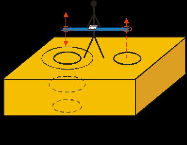
Fig. 1. Drawing describing the operation of the instrument in a homogeneous half space.
The instrument may be carried in two ways. When it is horizontal (Fig. 2), then the transmission coils (Tx) and the receiver (Rx) are horizontal, and the primary (inducing) field is vertical. This method of operation is called "vertical mode". The other option is when the instrument is tilted, the transmission coils and the receiver are vertical and the primary field is horizontal. The second operating method is called "horizontal mode". The penetration depth in the horizontal mode is approximately half the depth in the vertical mode. Additionally, the horizontal field is less sensitive to horizontal changes than the vertical field (Goldstein et al., 1990). 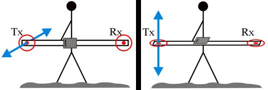
Fig. 2: Right diagram: vertical mode – the primary field is vertical (in blue), the transmitter coils and receiver are horizontal. Left diagram: horizontal mode – the primary field is horizontal, the transmitter coils and the receiver are vertical.
Time-based EM methods (TDEM)
These methods are based on an energy source that generates an alternating current (usually a step function) in a large source current loop (Fig. 3). The initial current in the source is generated according to the Biot-Savart's Law, a primary magnetic field around a source current loop. The transmitter (that is connected to the energy source and the current loop) stops the source current and renews it at a certain rate. The wave-pattern current is created as a result of repeated turnoffs turnons in the source current generation (Fig. 4).

According to Faraday's Law of Induction, a sudden, sharp turnoff of the current creates an electromotive force (EMF) as a result of the change in the primary magnetic field's flux. The EMF induced secondary electrical currents in the medium. These currents are dependent on their strength on the electrical resistivity of the subsurface.
The currents propagate in a diffusive manner into the subsurface; the longer the ellappsed time from the turnoff of the source current, a deeper the penetration into the subsurface is obtained, and information from the deeper layers is obtained. The secondary currents create a secondary magnetic field that alternating in time, producing an EMF, which is measured in the receiver coil (that is usually situated at the center of the source current loop, Fig. 4). The measurement is carried out in the absence of the primary magnetic field. The information from the depth is dependent on the ellapsed time since the turnoff of the source current.
Fig 4.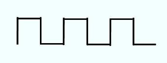
The TDEM method can be divided into two basic data acquisition methods:
- Profiling – which is used to acquire the distribution of electric resistivity in a lateral manner, in order to identify anomalies along the survey line.
- Sounding – vertical depth measurement. This method is used to measure the differences in the electric resistivity with depth, and in this respect, is the equivalent of drilling a borehole.
In the commonly used central loop method, the transmission loop is square shaped (at times, rectangular), with the side of the rectangle tens to hundreds of meters long, in accordance with the depth of the target and the required resolution. A series of points may be measured, creating a vertical section of the electrical conductivity (Fig. 5).
Presently existing TDEM systems include systems that operate in very shallow sections of the subsurface; some of these are used to detect metals. The systems are small, and can be operated by one person.
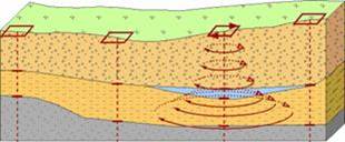
Fig. 5. Several TDEM measurements create an electrical conductivity section that describes the subsurface's structure.
Reference:
Ronen Amit, January 1991: Mapping of seawater intrusion into the coastal aquifer of Israel using the TDEM method. A composition written as part of the requirements for an M.Sc. degree in Geophysics and Planetary Sciences from Tel Aviv University, Israel.